This post will derive the transfer function for a bridged t-network, expressed using impedances, and will be the first of a series of posts I’ll be making as I’m learning about, and working on, a design for an analog drum machine similar to that of the famous Roland machines.
The post will begin with a short background for why the bridged t-network in particular will be examined. Then, the derivation of the transfer function will be given, followed by a simulation of the circuit to validate that the derived expression is correct.
I. Background
In the service manual for the tr-808 drum machine, the following principal diagram for the basic pulse-triggered sound generator can be found:

While the circuitry in the tr-808 is not as straight forward as in Fig 1, it is an excellent starting point for a study. By understanding the principal schematic, it creates the foundation for learning about the more complex and nuanced circuits in the actual hardware.
The sound generator consists of an operational amplifier (op-amp) and a feedback circuit consisting of the bridged t-network, which forms a bandpass filter with a high resonance. The filter acts as a damped oscillator (see Fig 2), and will self-oscillate at the resonance-frequency for a short time after being stimulated by an input-pulse. This is makes up the basic drum sound.

The circuit above (Fig 1) will be able to create a tom-like sound or a kick-like sound depending on the resonant frequency’s value, which is determined by the valeus of the circuit components.
II. Transfer function for the bridged t-network
The transfer function describes the relation between the components and the circuits’ behavior, and will be derived from the following diagram:

The transfer function is an expression for the ratio between the output voltage 


Deriving the transfer function from the schematic becomes a process of finding an expression for the output voltage as as a function of the input voltage, and factoring that expression.
The output voltage node and input voltage node are separated by the impedance 


To express the common-voltage we notice that 

where the total impedance 

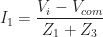
The current
![\begin{aligned} \displaystyle I_1 &= V_i \frac{1}{Z_1+Z_3}-V_{com}\frac{1}{Z_1+Z_3} \\[0.5em] \displaystyle &= V_i \frac{1}{Z_1+Z_3}-V_i\frac{Z_4}{Z_{tot}}\frac{1}{Z_1+Z_3} \\[0.5em] \end{aligned}](https://s0.wp.com/latex.php?latex=%5Cbegin%7Baligned%7D+%5Cdisplaystyle+I_1+%26%3D+V_i+%5Cfrac%7B1%7D%7BZ_1%2BZ_3%7D-V_%7Bcom%7D%5Cfrac%7B1%7D%7BZ_1%2BZ_3%7D+%5C%5C%5B0.5em%5D+%5Cdisplaystyle+%26%3D+V_i+%5Cfrac%7B1%7D%7BZ_1%2BZ_3%7D-V_i%5Cfrac%7BZ_4%7D%7BZ_%7Btot%7D%7D%5Cfrac%7B1%7D%7BZ_1%2BZ_3%7D+%5C%5C%5B0.5em%5D+%5Cend%7Baligned%7D+&bg=ffffff&fg=1a1a1a&s=0&c=20201002)
and then factored:
![\begin{aligned} \displaystyle &= \frac{V_i}{Z_1+Z_3} (1-\frac{Z_4}{Z_{tot}}) \\[0.5em] \displaystyle &= \frac{V_i}{Z_1+Z_3} (\frac{Z_{tot}-Z_4}{Z_{tot}}) \\[0.5em] \displaystyle &= \frac{V_i}{Z_1+Z_3} (\frac{Z_{(1+3)//2}}{Z_{tot}}) \\[0.5em] \end{aligned}](https://s0.wp.com/latex.php?latex=%5Cbegin%7Baligned%7D+%5Cdisplaystyle+%26%3D+%5Cfrac%7BV_i%7D%7BZ_1%2BZ_3%7D+%281-%5Cfrac%7BZ_4%7D%7BZ_%7Btot%7D%7D%29+%5C%5C%5B0.5em%5D+%5Cdisplaystyle+%26%3D+%5Cfrac%7BV_i%7D%7BZ_1%2BZ_3%7D+%28%5Cfrac%7BZ_%7Btot%7D-Z_4%7D%7BZ_%7Btot%7D%7D%29+%5C%5C%5B0.5em%5D+%5Cdisplaystyle+%26%3D+%5Cfrac%7BV_i%7D%7BZ_1%2BZ_3%7D+%28%5Cfrac%7BZ_%7B%281%2B3%29%2F%2F2%7D%7D%7BZ_%7Btot%7D%7D%29+%5C%5C%5B0.5em%5D+%5Cend%7Baligned%7D+&bg=ffffff&fg=1a1a1a&s=0&c=20201002)
By calculating the equivalent impedance
![\begin{aligned} \displaystyle Z_{(1+3)//2} &= \frac{(Z_1+Z_3)Z_2}{(Z_1+Z_3)+Z_2} \\[1em] \displaystyle Z_{tot} &= \frac{(Z_1+Z_3)Z_2}{(Z_1+Z_3)+Z_2}+Z4 \\[0.5em] &= \frac{(Z_1+Z_3)Z_2}{Z_1+Z_2+Z_3}+Z4\frac{(Z_1+Z_2+Z_3)}{(Z_1+Z_2+Z_3)} \\[0.5em] &= \frac{(Z_1+Z_3)Z_2+Z_4(Z_1+Z_2+Z_3)}{Z_1+Z_2+Z_3} \\[0.5em] \end{aligned}](https://s0.wp.com/latex.php?latex=%5Cbegin%7Baligned%7D+%5Cdisplaystyle+Z_%7B%281%2B3%29%2F%2F2%7D+%26%3D+%5Cfrac%7B%28Z_1%2BZ_3%29Z_2%7D%7B%28Z_1%2BZ_3%29%2BZ_2%7D+%5C%5C%5B1em%5D+%5Cdisplaystyle+Z_%7Btot%7D+%26%3D+%5Cfrac%7B%28Z_1%2BZ_3%29Z_2%7D%7B%28Z_1%2BZ_3%29%2BZ_2%7D%2BZ4+%5C%5C%5B0.5em%5D+%26%3D+%5Cfrac%7B%28Z_1%2BZ_3%29Z_2%7D%7BZ_1%2BZ_2%2BZ_3%7D%2BZ4%5Cfrac%7B%28Z_1%2BZ_2%2BZ_3%29%7D%7B%28Z_1%2BZ_2%2BZ_3%29%7D+%5C%5C%5B0.5em%5D+%26%3D+%5Cfrac%7B%28Z_1%2BZ_3%29Z_2%2BZ_4%28Z_1%2BZ_2%2BZ_3%29%7D%7BZ_1%2BZ_2%2BZ_3%7D+%5C%5C%5B0.5em%5D+%5Cend%7Baligned%7D+&bg=ffffff&fg=1a1a1a&s=0&c=20201002)
The impedance-quotient then becomes:
![\displaystyle \begin{aligned} \frac{Z_{(1+3)//2}}{Z_{tot}} &= \frac {\displaystyle \frac{(Z_1+Z_3)Z_2}{Z_1+Z_2+Z_3}} {\displaystyle \frac{(Z_1+Z_3)Z_2+Z_4(Z_1+Z_2+Z_3)}{Z_1+Z_2+Z_3}} \\[0.5em] &= \frac{(Z_1+Z_3)Z_2}{(Z_1+Z_3)Z_2+Z_4(Z_1+Z_2+Z_3)} \end{aligned}](https://s0.wp.com/latex.php?latex=%5Cdisplaystyle+%5Cbegin%7Baligned%7D+%5Cfrac%7BZ_%7B%281%2B3%29%2F%2F2%7D%7D%7BZ_%7Btot%7D%7D+%26%3D+%5Cfrac+%7B%5Cdisplaystyle+%5Cfrac%7B%28Z_1%2BZ_3%29Z_2%7D%7BZ_1%2BZ_2%2BZ_3%7D%7D+%7B%5Cdisplaystyle+%5Cfrac%7B%28Z_1%2BZ_3%29Z_2%2BZ_4%28Z_1%2BZ_2%2BZ_3%29%7D%7BZ_1%2BZ_2%2BZ_3%7D%7D+%5C%5C%5B0.5em%5D+%26%3D+%5Cfrac%7B%28Z_1%2BZ_3%29Z_2%7D%7B%28Z_1%2BZ_3%29Z_2%2BZ_4%28Z_1%2BZ_2%2BZ_3%29%7D+%5Cend%7Baligned%7D+&bg=ffffff&fg=1a1a1a&s=0&c=20201002)
The current
![\begin{aligned} \displaystyle I_1 &= \frac{V_i}{Z_1+Z_3} (\frac{Z_{(1+3)//2}}{Z_{tot}}) \\[0.7em] \displaystyle &= \frac{V_i}{(Z_1+Z_3)} \frac{(Z_1+Z_3)Z_2}{(Z_1+Z_3)Z_2+Z_4(Z_1+Z_2+Z_3)} \\[0.7em] \displaystyle &= V_i \frac{Z_2}{(Z_1+Z_3)Z_2+Z_4(Z_1+Z_2+Z_3)} \\[0.7em] \end{aligned}](https://s0.wp.com/latex.php?latex=%5Cbegin%7Baligned%7D+%5Cdisplaystyle+I_1+%26%3D+%5Cfrac%7BV_i%7D%7BZ_1%2BZ_3%7D+%28%5Cfrac%7BZ_%7B%281%2B3%29%2F%2F2%7D%7D%7BZ_%7Btot%7D%7D%29+%5C%5C%5B0.7em%5D+%5Cdisplaystyle+%26%3D+%5Cfrac%7BV_i%7D%7B%28Z_1%2BZ_3%29%7D+%5Cfrac%7B%28Z_1%2BZ_3%29Z_2%7D%7B%28Z_1%2BZ_3%29Z_2%2BZ_4%28Z_1%2BZ_2%2BZ_3%29%7D+%5C%5C%5B0.7em%5D+%5Cdisplaystyle+%26%3D+V_i+%5Cfrac%7BZ_2%7D%7B%28Z_1%2BZ_3%29Z_2%2BZ_4%28Z_1%2BZ_2%2BZ_3%29%7D+%5C%5C%5B0.7em%5D+%5Cend%7Baligned%7D+&bg=ffffff&fg=1a1a1a&s=0&c=20201002)
Finally, we can return to the output voltage expression, and factor out
![\begin{aligned} \displaystyle V_o &= V_i-I_1 Z_1 \\[0.5em] \displaystyle &= V_i-V_i \frac{Z_2}{(Z_1+Z_3)Z_2+Z_4(Z_1+Z_2+Z_3)} Z_1 \\[0.5em] \displaystyle &= V_i \left(1-\frac{Z_1 Z_2}{(Z_1+Z_3)Z_2+Z_4(Z_1+Z_2+Z_3)}\right) \\[0.5em] \end{aligned}](https://s0.wp.com/latex.php?latex=%5Cbegin%7Baligned%7D+%5Cdisplaystyle+V_o+%26%3D+V_i-I_1+Z_1+%5C%5C%5B0.5em%5D+%5Cdisplaystyle+%26%3D+V_i-V_i+%5Cfrac%7BZ_2%7D%7B%28Z_1%2BZ_3%29Z_2%2BZ_4%28Z_1%2BZ_2%2BZ_3%29%7D+Z_1+%5C%5C%5B0.5em%5D+%5Cdisplaystyle+%26%3D+V_i+%5Cleft%281-%5Cfrac%7BZ_1+Z_2%7D%7B%28Z_1%2BZ_3%29Z_2%2BZ_4%28Z_1%2BZ_2%2BZ_3%29%7D%5Cright%29+%5C%5C%5B0.5em%5D+%5Cend%7Baligned%7D+&bg=ffffff&fg=1a1a1a&s=0&c=20201002)
and then calculate the difference inside the parentheses by expanding the leading 1-term:
![\begin{aligned} \displaystyle &= V_i \frac{(Z_1+Z_3)Z_2+Z_4(Z_1+Z_2+Z_3)-Z_1 Z_2}{(Z_1+Z_3)Z_2+Z_4(Z_1+Z_2+Z_3)} \\[0.5em] \displaystyle &= V_i \frac{Z_1 Z_2+Z_2 Z_3 +Z_4(Z_1+Z_2+Z_3)-Z_1 Z_2}{(Z_1+Z_3)Z_2+Z_4(Z_1+Z_2+Z_3)} \\[0.5em] \displaystyle &= V_i \frac{Z_2 Z_3 +Z_4(Z_1+Z_2+Z_3)}{(Z_1+Z_3)Z_2+Z_4(Z_1+Z_2+Z_3)} \\[0.5em] \end{aligned}](https://s0.wp.com/latex.php?latex=%5Cbegin%7Baligned%7D+%5Cdisplaystyle+%26%3D+V_i+%5Cfrac%7B%28Z_1%2BZ_3%29Z_2%2BZ_4%28Z_1%2BZ_2%2BZ_3%29-Z_1+Z_2%7D%7B%28Z_1%2BZ_3%29Z_2%2BZ_4%28Z_1%2BZ_2%2BZ_3%29%7D+%5C%5C%5B0.5em%5D+%5Cdisplaystyle+%26%3D+V_i+%5Cfrac%7BZ_1+Z_2%2BZ_2+Z_3+%2BZ_4%28Z_1%2BZ_2%2BZ_3%29-Z_1+Z_2%7D%7B%28Z_1%2BZ_3%29Z_2%2BZ_4%28Z_1%2BZ_2%2BZ_3%29%7D+%5C%5C%5B0.5em%5D+%5Cdisplaystyle+%26%3D+V_i+%5Cfrac%7BZ_2+Z_3+%2BZ_4%28Z_1%2BZ_2%2BZ_3%29%7D%7B%28Z_1%2BZ_3%29Z_2%2BZ_4%28Z_1%2BZ_2%2BZ_3%29%7D+%5C%5C%5B0.5em%5D+%5Cend%7Baligned%7D+&bg=ffffff&fg=1a1a1a&s=0&c=20201002)
With the original expression fully factorized, the transfer function can now be expressed:
![\begin{aligned} \displaystyle \frac{V_o}{V_i} &= \frac{Z_2 Z_3 +Z_4(Z_1+Z_2+Z_3)}{(Z_1+Z_3)Z_2+Z_4(Z_1+Z_2+Z_3)} \\[0.5em] \end{aligned}](https://s0.wp.com/latex.php?latex=%5Cbegin%7Baligned%7D+%5Cdisplaystyle+%5Cfrac%7BV_o%7D%7BV_i%7D+%26%3D+%5Cfrac%7BZ_2+Z_3+%2BZ_4%28Z_1%2BZ_2%2BZ_3%29%7D%7B%28Z_1%2BZ_3%29Z_2%2BZ_4%28Z_1%2BZ_2%2BZ_3%29%7D+%5C%5C%5B0.5em%5D+%5Cend%7Baligned%7D+&bg=ffffff&fg=1a1a1a&s=0&c=20201002)
And the parenthesises expanded:
![\begin{aligned} \displaystyle \frac{V_o}{V_i} &= \frac{Z_1 Z_4+Z_2 Z_3 +Z_2 Z_4+Z_3 Z_4}{Z_1 Z_2+Z_1 Z_4+Z_2 Z_3+Z_2 Z_4+Z_3 Z_4} \\[0.5em] \end{aligned}](https://s0.wp.com/latex.php?latex=%5Cbegin%7Baligned%7D+%5Cdisplaystyle+%5Cfrac%7BV_o%7D%7BV_i%7D+%26%3D+%5Cfrac%7BZ_1+Z_4%2BZ_2+Z_3+%2BZ_2+Z_4%2BZ_3+Z_4%7D%7BZ_1+Z_2%2BZ_1+Z_4%2BZ_2+Z_3%2BZ_2+Z_4%2BZ_3+Z_4%7D+%5C%5C%5B0.5em%5D+%5Cend%7Baligned%7D+&bg=ffffff&fg=1a1a1a&s=0&c=20201002)
The transfer function for the schematic has now been derived.
III. Validating the transfer function with a simulation
In order to validate that the transfer function is correct, it will be tested using resistive values and compared to the output from the simulation software PSpice.
A simple straight forward test is to simply define all the impedances to 1kΩ:
![\begin{aligned} \displaystyle \frac{V_o}{V_i}(Z_i=1k) &= \frac{(1+1+1+1)k}{(1+1+1+1+1)k} = \frac{4k}{5k} = 0.8\\[0.5em] \end{aligned}](https://s0.wp.com/latex.php?latex=%5Cbegin%7Baligned%7D+%5Cdisplaystyle+%5Cfrac%7BV_o%7D%7BV_i%7D%28Z_i%3D1k%29+%26%3D+%5Cfrac%7B%281%2B1%2B1%2B1%29k%7D%7B%281%2B1%2B1%2B1%2B1%29k%7D+%3D+%5Cfrac%7B4k%7D%7B5k%7D+%3D+0.8%5C%5C%5B0.5em%5D+%5Cend%7Baligned%7D+&bg=ffffff&fg=1a1a1a&s=0&c=20201002)

With the input voltage
In order to make sure this isn’t just a fluke result, another set of test-values can be defined:
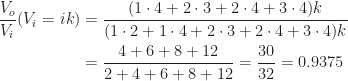

For this second test the result is also the expected one, with an input voltage
IV. Conclusion
A valid transfer function for the bridged t-network has been derived for impedances. In order to analyze its oscillation properties and bode diagram, those impedances need to be defined using resistors 

This will be explored in the next part.


